I’ve had my blade-making operation shut down for the last 2 years, because my old forge began developing awkward melted holes in the shell, which allowed long burning jets of propane to go shooting out all over the place.
Because of the resurgence in interest in blade-smithing and related fun, it’s hard to get a new forge anymore; the good ones are wait-listed and the bad ones are useless. There is one obvious answer: do it myself. I posted a while back about obtaining some lengths of 16″ diameter 3/8″ thick steel pipe, drawing some assembly sketches, and lugging them down to the fabricators in Clearfield. The folks at TD Fabricating, I must say, are very patient with me. [stderr]
They did a bang-up job and then I let it sit in the front hall at the shop for over a year. A lot of it was subliminally (No, I am not kidding!) designing the remainder of the build, but it was also just that I was busy with a lot of other things too. I kept pushing back and pushing back, waiting until I had the right mix of design ideas. This is a serious issue: when you’re casting several hundred pounds of refractory cement into another hundred+ pounds of steel pipe, you don’t want to be having to go rent a jack-hammer. Or start over. The “start over” plan consists of loading the thing into the back of my truck, driving to Novey’s scrap metal, and tipping it out the back with a pry-bar. This is not an easy project to start over.
One thing not shown is that, to make the cement stay in place, I used Mr Happy Dancing Bandsaw to cut a big length of “L” bracket into 1/4″ slices that I MIG-welded into the inside. That’ll give the cement something to hold onto – but if I have to hammer the cement out, I’ll be working against my own welded brackets.
I’m not going to show a lot of this stuff because I was too doggone busy making it to take pictures. Also, some took 3 hands and I didn’t have a spare for my camera-phone. But, there are a few things to think about in the whole process: absolutely every step has to be designed to prevent concrete from mechanically locking another piece of the assembly from assembling correctly. Once that has all been thoroughly thought through, it’s easy. Then, comes having the confidence to believe it is all thoroughly thought through. Let me spoiler: it all was except for one part that I nearly blew, but recovered just in time.
I’ve watched people try to cast refractory jackets and screw the process up, and that was extra incentive to not do that. So let’s get into it. There’s a central tube, and two caps. Each cap has a unique vent-hole that needs a custom form. Then, the central tube needs forms for casting two layers of refractory while leaving a perfect-shaped hole for the ribbon burner assembly. There are a lot of non-moving parts, and you may remember my non-prediliction for measuring. All of this was assembled using brainpower instead of tape measures and whatnot.
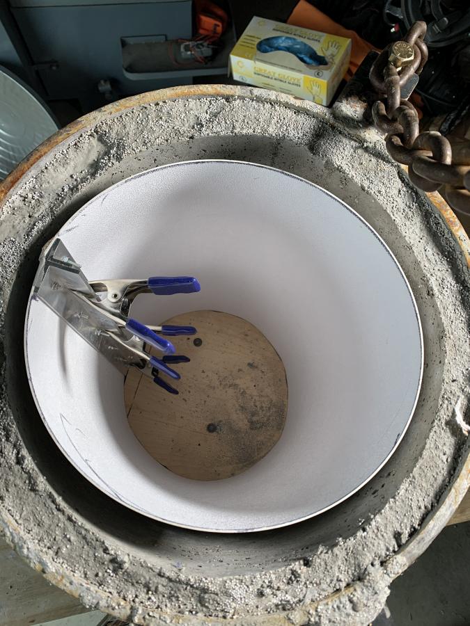
That picture above is a bit of a spoiler. I don’t have a picture of what the form for the first layer of refractory looked like. But it looked just like the form for the second layer: a sheet of ABS plastic wrapped around plywood discs to keep the weight of the cement from collapsing the form, with a clamping system made of two aluminum L-extrusions. Each of the plywood disks had a “foot” on it that kept it from falling down onto the next, and there were slots that allowed it to slip over the L-extrusions. The idea behind this system was that I was not going to have mechanically locked forms stuck to my concrete. I was going to take a hold of a bolt sticking up from each plywood disk, pull it up and out, then unclip the L-extrusions, and roll them up inside thereby detaching them from the cement and making everything super easy.
I did two separate castings – one a light “foamcrete” for insulation and the innermost a layer of “mizzou” high temperature fire cement. So, the “foamcrete” could be a bit rough-surfaced to allow the mizzou to bond, and the “foamcrete” is hooked around the L-brackets welded to the interior. The “foamcreate” is cast-o-lite from Harbison Walker, which has a max rated temperature of 2,500F which is just on the edge of not good enough. It cannot be directly exposed to a forge interior or it will eventually turn to dust (carcinogenic dust, at that). The additional foam is pillow stuffing expanded styrofoam beads. Stirring those into refractory is a popular trick for making your forge smell like shit for a while, lightening it, and improving the insulation properties of the cast-o-lite. Above you can see the form assembly system and the first layer of refractory.

Here is one of the ends (the front) – the form here is a piece of plywood (whole thing resting on) with white closed cell foam, that I sculpted on Mr Happy Dancing Bandsaw, sitting in the center. That’s the “foamcrete” layer. When it was cured, I took a pair of pliers and shredded the closed cell foam out until I could hit the remains with a hammer and the form popped free. Then, it was time to build the second forms, which I had to visualize so they would make a concrete jacket that fit correctly but was smaller and completely covered the foamcrete. After spending two years thinking about this stuff, it wasn’t too hard to make the forms.
And, right about here is where I nearly screwed up.
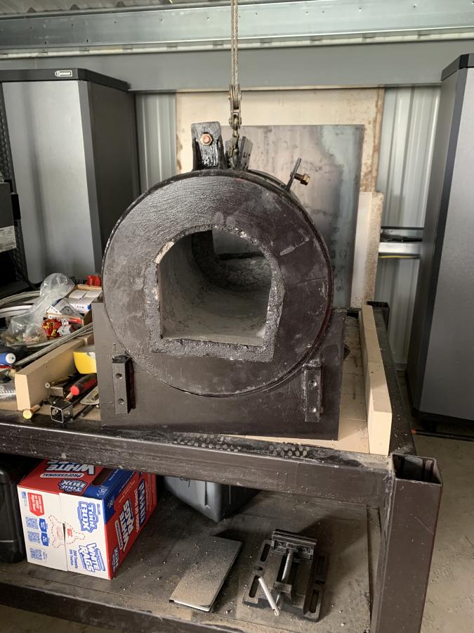
So, the forge body weighs a lot. The ends do, too. I realized I would be pretty dang stupid if I did the cement casting at the studio and then had to move the now cement-filled components. I could have probably gotten help but help always comes with burdens, so I moved the whole thing myself, before it was assembled. That was another one of those “stand around thinking for a few days while doing something else” and I remembered I had an old A/V cart that was just about the height of the tailbed of my truck. Just a bit higher. Perfect! That meant I could put a “come along” on a beam over the forge body, hook a chain to it, lift it, put it down on the cart, and push the whole mass down to my truck and slide it in! The process went perfectly for all 3 pieces, and it was time for everything to move to the hot shed.
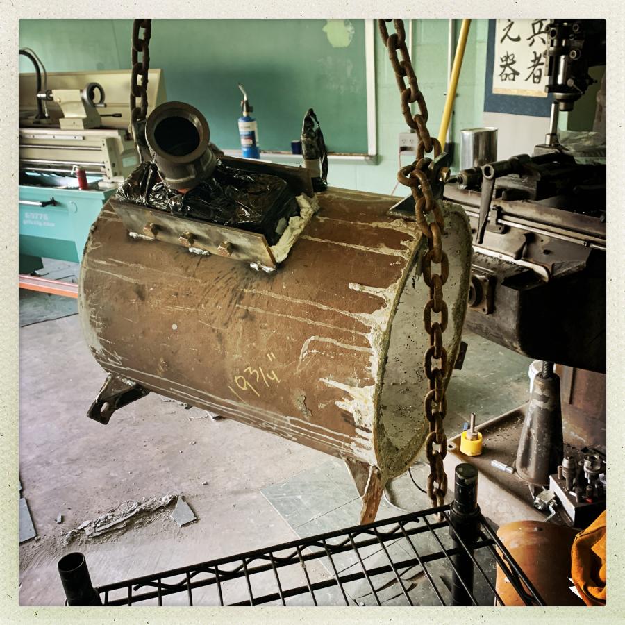
In the picture above, you can see the ribbon burner, wrapped in plastic, to keep cement from sticking to it. I hammered paper towels down around it against the form so that, when the form is released, there will maybe be a perfectly-shaped hole for the ribbon burner. The second layer of refractory is much heavier than the “foamcrete” and I don’t know if I’d have been able to move the thing if I had not thought of moving it before the pour.
Another view, because I can.
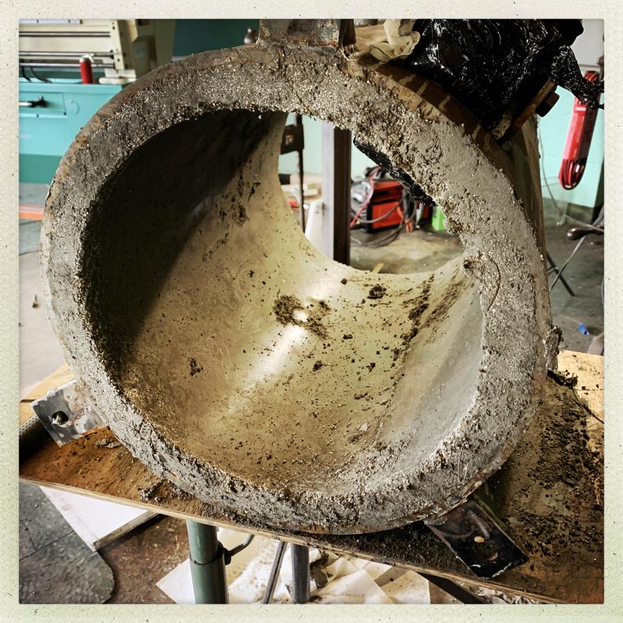
You don’t have to look at both ends of these, but I think it’s kind of neat how it worked out. That’s the first layer:
The challenge for Layer 2 is to make a form that will de-mold and will produce a nicely solid refractory casting. Piece of cake! I have to admit that some of this was testing to see if my brain has recovered fully (I think it has) because I had to do some visualizing of 3-D solids interacting. Then, I cut the foam on Mr Happy Dancing Bandsaw with the table at a slight angle to produce a non-mechanically-locking version of the form for the concrete.

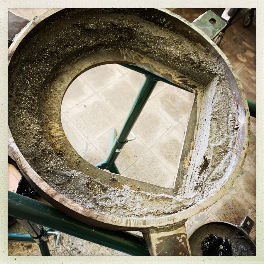
Paint happened. By this point, all the refractory is cast and the paint is a kind of victory lap. Here’s what one of the ends looks like:

I think that turned out pretty darned elegant, if I may say so myself. That’s 1″ of “mizzou” 3000F-capable refractory cast onto 1″ of “foamcrete” cast-o-lite. And my form de-molded without splitting anything. From there the full assembly of the beast is a matter of making a cement slurry on the flats and bolting the front and back onto the tube.
But – wait – the “ears” don’t line up in the front. How can this be? Well, when I sketched it out, I offset the ear so it wouldn’t interfere with the ribbon burner, and I forgot that. Then, I decided to cut out the front opening a bit more, and did it rotated 33 degrees, so it would not assemble properly. What to do? What to do? Simple, really: grab an angle grinder, mount a diamond wheel, cut the ear off, get out the stick welder and put the ear in the right place, then it’s time for that second coat of paint anyway!
Getting the damn thing onto the stand was not fun. I almost got my finger under it, in fact. But eventually after some prying and poking, it was there. Then, I realized I needed it 6″ over to my left, so I’d have room for the pressure/feed system. I put down some boards over the firebrick and used a great big pry-bar to creep it into position, pyramid-builder style.

The “front porch” was a last-minute design addition and, without it, the forge would be nearly unusuable. It turns out that the porch is great for piling fire-bricks on to keep the pressurized, burning, propane, from forming a death-beam pointing right at the human trying to operate the thing. I will get to that later but let’s say for now that this thing runs a bit hot.
That’s all for tonight. Part 2, I’ll get into the gas and fan feed system.
Amazing, and looking really good! I mean amazing because that’s really Moving Heavy Things. I’ve been advised that every man in Minnesota knows that moving heavy things really impresses women. Guess it works for men in Pennsylvania as well, I am very impressed.
Also that’s super clever how you got the form out of the center.
Can’t wait to see that baby fired up and going!
That thing is huge. Happy forging!
FWIW, your writing seems perfectly OK to me these last few posts.