I took a couple days off and worked slowly on the high-intensity parts like re-shaping the top curve. I measured and the sawz-all was giving me about 3″/minute and my forearms and hands would start cramping after about 15 minutes. All in all, it was not too bad (good grip strength exercise!) but it was hardly what I would call “fun.”
Final assembly was definitely going to be no “fun” especially since I decided to solo it. That meant that things were going to have to fit well, because there was no way I was going to be able to jiggle-fiddle fit a 170lb beam while I was supporting it 13 feet off the ground. So, I used some of the downtime to figure out the best way of fitting the assembly so that it would be precise but I wouldn’t have a lot of fancy measuring and thinking to do. It’s another job for “experiential assembly” – make it so that it cannot not fit because you assemble each piece to the other pieces in the correct order.
Step 1, I put the lower top-beam in place (thereby making sure it fit!) and ran an 12″ long 5/8″ drill bit through the lower top-beam and into the top of the post. That way I knew the lower top-beam and the post hole were registered to eachother.
After examining a bunch of Japanese vintage torii, I concluded that the lower top-beam serves as a stiffener upon which the upper top-beam is constructed and mounted. In fact some torii have little roofs or multiple layers of upper beams. Those are attached to the stiffener – the lower top-beam which is often pegged and roped to the top of the pole. In other words the upper top-beam floats above the pole, resting on the lower top-beam.
Step 2, I took the lower top-beam down again and flipped the upper top-beam on its top edge, positioned the lower top-beam on top of it, then used the holes I had just drilled as guide-holes to drill as 12″ deep hole in the upper top-beam. Presumably all the holes were now in correct alignment. Presumably all the holes were now 24″ deep or more (because the lower top-beam was 5″ thick) and that would admit a 24″ chunk of 1/2″ rebar as a central post mount.
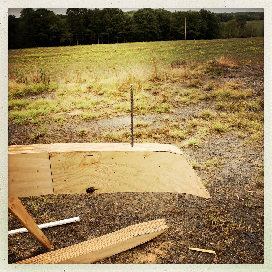
Step 3, I put a bunch of glue in the hole of the upper top-beam and dropped the rebar in to let the whole thing cure. In retrospect, final assembly would have been easier if I had glued the rebar into the post and lower top-beam, but I had the thought, at the time, that the piece of rebar would be handy for tying a rope around to the rope wouldn’t slide along the beam and it wouldn’t fall on any part of me. As it happened, that was a good idea, but I should have used a screw instead, and put the rebar in the post. If any of you ever decide to do one of these, now you’ll know.
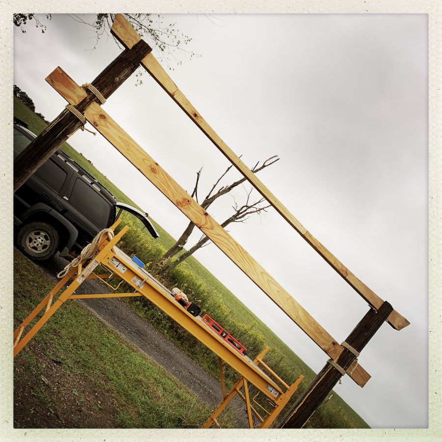
Step 4, now it was time to assemble the top beams. I looped a rope around the rebar on one end, then climbed the ladder, hauling that end of the beam up with me (the other end dragged in the mud and got muddy). I looped the rope loosely around the pole and lower top-beam so it could be shifted a bit, but wouldn’t fall on me. Actually, in order to reduce the chance of me getting tangled in the rope, I lifted the beam first, then propped it, ran down and got the rope, and did the roping quickly.
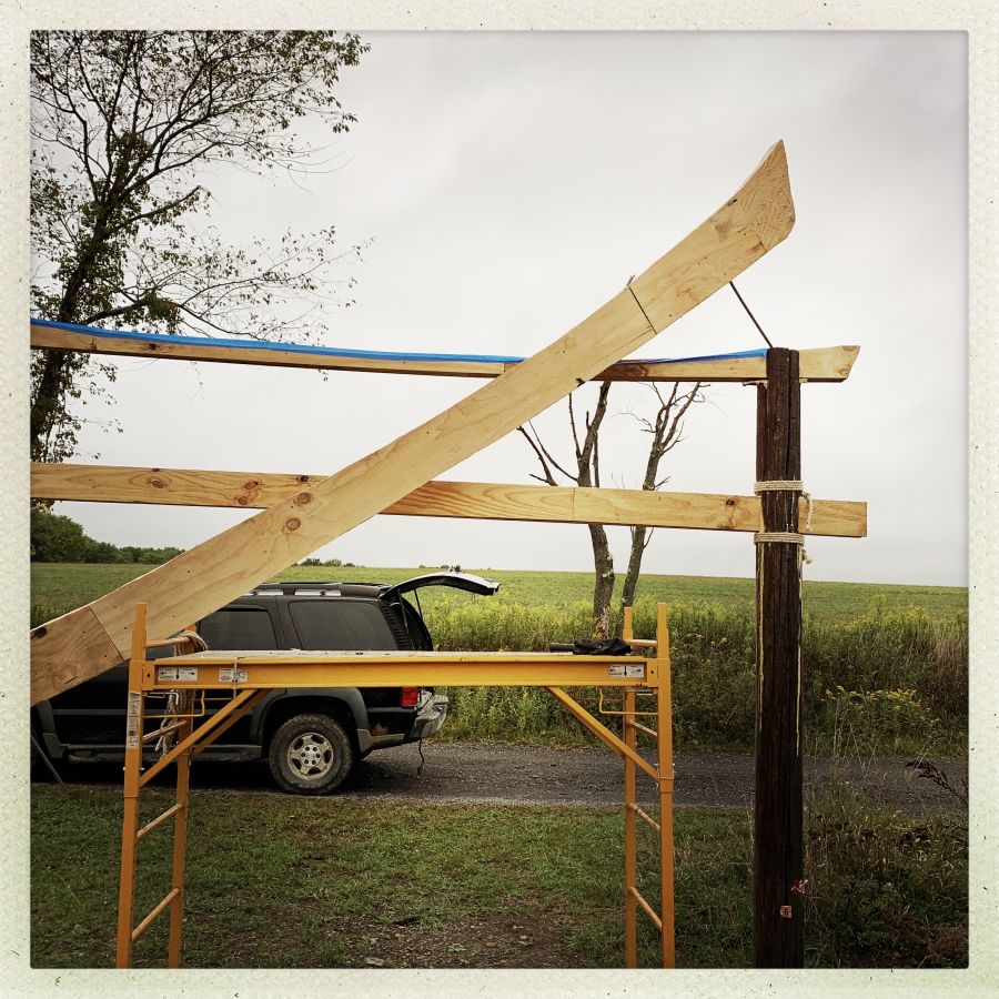
Step 5: Long things are easy to turn into a Type-1 lever, if you’re into trying goofy things like this. So, from there it was simply a matter of running to the other end, lifting the beam (one-handed, while holding a death-grip on the pole) and maneuvering the rebar into the hole that was ready for it. That left the first end balancing awkwardly on the rebar peg, trying to wobble from side to side, but I didn’t have to worry about the whole thing coming crashing down because of the safety rope.
And speaking of safety rope, I reasoned correctly that lifting the beam on my latter or gantry might put angular pressure on the ladder – especially if the beam slipped – and I’d get launched into the weeds with the ladder. So, I used more rope to tie the ladder to the pole. Then, my only problem was making sure the beam didn’t fall and do something like crush my hand or foot. When I’m working with dangerous set-ups I try to design things so I only have a minimum number of things to worry about (i.e.: “don’t let go of the pole and if the beam drops, dodge it”) I drill myself mentally with the rules of the situation and, so far, that has worked for 57 years more or less without dramatic failures.

Step 6: From there it was a simple matter of running back and forth and applying whacks with my forging hammer (which I brought from the shop) until the rebar was seated nicely. You can see a bunch of blue masking tape – I used that to make a “dam” along the side of the lower top-beam, so I could pour a bunch of foaming adhesive in there, so it’d foam up and make a nice seal. I also managed to get the shit all over my hair and hands, then put my gloves on to protect my hands and now I have leather fingernail appliques.
Step 7: I used pieces of rope, running over streams of foaming glue, stapled and tied, to reinforce the pole and reinforce the join between the upper top-beam and the lower top-beam. There are also 5 10″ lag screws running from the lower beam up into the upper. There is also lots of foaming glue on the tops of the poles and in my hair, on my shirt, and my hands. I am fairly sure that the medieval Japanese did not use foaming glue and I know why.

I have been liberal – nay, a libertine – with the foaming glue but that’s because the whole thing is going to get a coat of liquid fiberglass resin on the upper surfaces (and some of the foam) followed by a coat of black porch paint (maybe 2, depends how much I can do with a gallon) and then a coat of cinnabar red porch paint. I hope the red sort of ages to show the black, though I may do something like leave the lower top-beam black and the ropes, or something like that. I don’t know, yet. I will decide in the moment.
Many torii gates have a message on a plaque that sits between the upper beam and middle beam. I am talking to a Japanese friend who has some calligraphy skills about a scannable logo that I can have water-jet cut or something (maybe do it by hand with a jeweler’s saw) but that will take time. The message I am considering is “If it doesn’t fit, hammer it” which, I think, is a good message.

Naturally, all this served to distract me from what I am supposed to be doing, which is finishing a commissioned puuko, and making the doors for the other side of the shop. We are now entering into the time of year when I enjoy working outside (rain! mud! yay!) so I do expect to have the doors done and in place within a few weeks.
And, naturally, when I sent a picture of this to my friend DJ Mixmaster Mike, Mike said, “needs some of those stone lanterns” and I immediately realized that I could use the fiberglass screen reinforcement trick I used on my lathe centers, to make them out of reinforced cement. Maybe instead of using traditional hole-shapes, I could use the shapes of Playstation controls or something. Make the originals in 4 sides out of plywood and cast concrete into rammed sand molds. Aaaaaaaaaaand that’s how Marcus gets sidetracked. What did you say, invade Russia? It’s the perfect time of year, it’s not too hot, let’s go!
Glue-soaked wrapped rope is incredibly tough stuff, I’m just sayin’.
鳥居⛩だ!
(obviously, now)
Looking good already, glad you managed to put it together without hurting yourself.
Hmm, this is uncomfortably close to “The nail that sticks out gets hammered down.” (出る釘は打たれる)
Can’t wait to see it finished. I’m so jealous.
Marcus, I’m sure you know the correct saying is “If it doesn’t fit, use a bigger hammer”.
Looks really good!
I agree with @3 Ridana. That saying is a big deal in Japan. Someone who knows Japanese will assume you meant that saying instead of what you meant, and just got it wrong because you are a weeaboo. You are the square peg that tells the round hole to fuck off. It is not the same.
Most torii do not have fixed characters on them IMO. Instead, you might find it fun to print geometry problems (totally a thing!) and stick one on every once in a while.
That is marvellous, and I did not guess what it was until very late.
Your way of approaching this kind of project baffles be, though. Where you’d glue up a large chunk of plywood and then freehand-sawzall the shape through I-don’t-know-how-many inches of now-solid wood, I’d draw the shape, fiddle with it until I was happy with it, plan how it would be assembled out of sheets of plywood, split the drawing into parts, cut the sheets individually (with holes for alignment pegs), and only then glue them up. Also, I would use a CNC router table, because (a) I have one, (b) I’m lazy, and (c) I don’t want to mess up my wrist jigsawing a kilometre through 18 mm plywood.
cvoinescu@#7:
Your way of approaching this kind of project baffles be, though. Where you’d glue up a large chunk of plywood and then freehand-sawzall the shape through I-don’t-know-how-many inches of now-solid wood, I’d draw the shape, fiddle with it until I was happy with it, plan how it would be assembled out of sheets of plywood, split the drawing into parts, cut the sheets individually (with holes for alignment pegs), and only then glue them up. Also, I would use a CNC router table, because (a) I have one, (b) I’m lazy, and (c) I don’t want to mess up my wrist jigsawing a kilometre through 18 mm plywood.
Having a CNC table helps a lot. I have a huge and mighty bandsaw and normally, I would assemble my object and then just bang it out on the bandsaw. That’s where I screwed up – a 13 foot, 170lb beam is unwieldy as hell.
I did think about cutting the pieces separately and laying them up, but I felt that the edge would be cleaner if I did the layup first and then the cut. That’s how it worked out but I agree with you that I took on a lot of extra work.