After my new forge lining has dried, I have coated the inside with about 5 mm of fireclay, nothing special about that. Then I have tested it and I was gravely disappointed – my puny little burner was not up to snuff and was unable to reach the 1050°C that I need. Funny, that, the inside volume should be about the same as in the previous model, where it did reach the temperature, albeit after a long time and with difficulty.
So I have decided to build a new burner and I am going to describe how. But this time first a disclaimer: This article is meant for entertainment purposes only. It is not meant to be a set of how-to instructions and I do not encourage anyone to do what I have done here. Propane gas can be dangerous if not handled properly and if you decide to reproduce or imitate anything shown here, you do so at your own risk.
Nevermind that, there is a lot of articles and videos on the interweb how to build a forge burner, but it became pretty quickly clear to me that none of it is what I actually want. So I proceeded to build a prototype to test what works and what does not.

© Charly, all rights reserved. Click for full size.
I wanted to retain the handle from my store-bought soldering burner, so I took the burner part off and I cobbled together some stuff instead of it from various plumbing parts. Luckily the burner is attached to the handle with standard 3/8″ thread (yes, piping in EU is the one exception where imperial units still prevail).
The prototype was working reasonably well, it reached a temperature of 1050°C that I need for hardening N690 easily and it heated up the whole inside volume of the forge fairly regularly. It is actually this burner that I have used to harden the Badgermascus this weekend. But due to its cobbled-together nature, figuring things out as I went along, the air-regulation did not work so well, I could not cut it off completely. So I have decided to take the information learned and build a completely new one. I went to the store once more and I bought new stuff, this time knowing what I am aiming for.
© Charly, all rights reserved. Click for full size.
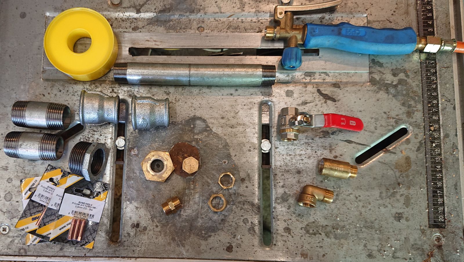
From left top to right down:
Propane-grade PTFE sealing tape, 1x 3/4″ x 9″ nipple, the handle from my soldering burner, 2x 1″x2,5″ nipple, 2x 1″ to 3/4″ female/female reduction, 1x 3/8″ ball valve, 1x 1″ to 5/4″ female/male reduction, 1x 1″ brass plug (drilled already – was used in the prototype), 1x 3/8″ brass plug, 1x 3/8″ brass nipple, 2x 3/8″ brass nut, 1x 3/8″ brass ellbow, 1x 3/8″ 2″ brass extension and various sizes of MIG-tips – 0.6, 0.8, 0.9 and 1.0 mm.
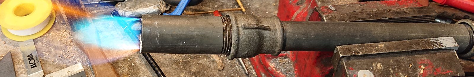
Unfortunately, all the steel piping was galvanized because that is the only type the local store was selling. That should not be a problem, because as you can be seen on the prototype, only the very end of the burner gets hot, the rest is pretty efficiently cooled by the flowing propane and air mixture. And I always work outside or near an open door. But I did not want to take any risks and I have decided to burn and brush off as much of the zinc as I could.
After that, I proceeded with the build. I started with the easy part – the brass fittings.

© Charly, all rights reserved. Click for full size.

© Charly, all rights reserved. Click for full size.
As you can see, I have drilled holes into both brass plugs – in the 1″ a hole big enough for the brass nipple thread to come through, and in the smaller one an M6 hole for the MIG tip to screw into. All connections are sealed with the PTFE tape and I have tested them in water for any leaks (I had to redo two of them). The rest of the burner need not be sealed, but everything before the nozzle must be completely tight. The ball valve is there as emergency shut-off, the handle has a needle-valve for fine regulation and the brass nuts serve as counters to lock the elbow joint and the ball valve in place so they cannot change position.
The air-regulation was the most labor-intensive part. I have taken the male/female reduction and I have ground out almost all of the inner thread so that I can screw it backward over the short 1″ nipple. I have only left 2 turns of the thread left but I filed even that down a bit so it turns very easily. Then I have screwed the reduction on the nipple as far as it would go and I drilled four 4 mm pilot holes through both. Then I unscrewed them and I widened all the holes to 12 mm.

© Charly, all rights reserved. Click for full size.
Here you can see the air regulation assembled in open position. I have added an M6 wing screw to be able to lock the reduction in place.
I did not take picture of the next step, but that consisted merely from screwing the two 1″ to 3/4″ reductions on both ends of the long 3/4″ nipple and onto the air-regulator and the air-regulator onto the big brass plug.

© Charly, all rights reserved. Click for full size.
To get better mixing of gasses and to slow the flow a bit I have crafted a small diffuser. That is just a piece of mild-steel with a mesh of holes drilled in it as depicted here. I have locked the diffuser in place at the flame end of the burner with a piece of cut-off thread.

© Charly, all rights reserved. Click for full size.
With this, the burner is de-facto functional, but it cannot be connected to the forge and it has a tendency for backfire, especially when the supply is quickly cut-off or reduced. To solve both of these problems I have intended to use the second 1″ nipple, but it has proven to be too short. So I took the 1″ pipe from the prototype, I cut it to the proper length and on the outer end, I have fixed inside fine steel mesh between two tightly-fitting pieces of pipe. Nothing fancy just pressed together.

© Charly, all rights reserved. Click for full size.
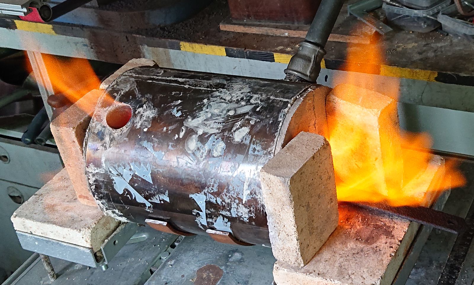
After that, I could assemble the whole thing and test it. In free air, the burner tended to blow the flame away at full setting still, but that could be eventually solved if I needed to (with another diffuser closer to the mesh).
© Charly, all rights reserved. Click for full size.
However, I do not need to, because when inserted into the inlet of the forge, this is not a problem anymore. The flame creates a nice vortex, and unless I run really full monty, most of the fuel burns inside the forge.

Nice flame vortex © Charly, all rights reserved. Click for full size.

A chunk of steel at 1100°C © Charly, all rights reserved. Click for full size.
When fitted with 0.6 mm MIG-tip I can reach 1050°C easily, with the 1.0 mm tip I have reached 1100°C but not more. To get above that I guess I would need a forge with bigger inner volume to get better fuel combustion. 1100°C is still not quite enough for forging damascus, although it is ample for my current needs.
So let us end with a picture of the dragon’s breath I got with 1.0 mm nozzle at full gas.
© Charly, all rights reserved. Click for full size.
Aaaah there is great pleasure for me in using things in ways they are not supposed to be. Oxy acetylene torch tip? Sure, put it in the lathe and drill the hole to 3mm so LOTS of propane can fit through it! It’s a controlled explosion and who doesn’t like fire?
You’re a good example of the saying ‘necessity is the mother of invention’.